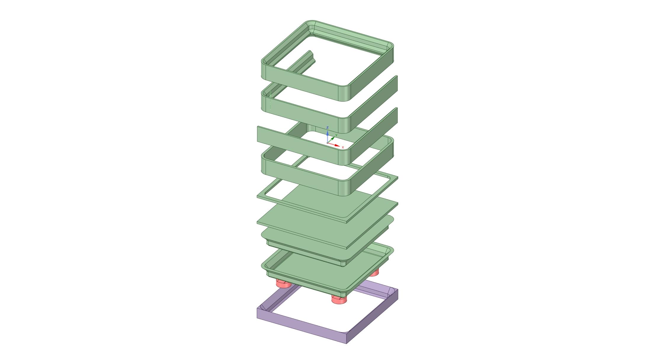
This is an exploded template of the components required to assemble a Gridfinity design by Zack Freedman. It is used with a CAD program to select, copy and assemble what is needed to create a Gridfinity design. If you don't want to, or can't, use one of the parametric design tools, this is an alternative.
I created this template because my CAD (Design Spark Mechanical) is not compatible with the parametric tools. I also found I was continually needing the basic components now contained in the exploded model.
The model includes a 42mm square plate with square corners. This plate joins adjacent Gridfinity cubes. If this plate is not included, there will be a small gap between cubes. On external corners, the plate corners need to be rounded to match the base and walls. This plate is not required for 1x1 cubes.
The walls are 1U (7mm) high. Stretch them to suit your application.
The top rim is optional for use with open top cubes. It reinforces the rim without affecting the cube capacity.
There is a solid base, when a flat bottom surface is required. There is also a shelled base that minimises the amount of plastic used.
Note the magnets are intended to be used as cutting objects. They are moved into the solid base and cut out the recesses for the magnets. How that is done will depend on your CAD program. To date, none of my Gridfinity cases includes magnets because they have not been needed.
The bottom object is a simple, no magnet, 1x1 support grid. Copy/paste this support to create any size/shape of grid.
I have provided files in a number of different formats that should be usable with a variety of CAD programs.

